


More first order systems
Frequency: the other side of the coin


When I was at the university, most Signals and Systems lectures started with the professor saying: «Let us consider a linear, time-invariant (LTI) system...». Only after long time I have been able to understood what this really means.
Let us consider a LTI system with a single input and a single output. The nature of the input and output may be any. Could be voltage but also temperature, light, weight, energy. Input and output can have different natures: you can inject a current and obtain temperature or give light and obtain electrical current.
A system is linear if for double amount of stimulus we get double response, whichever amplitude is. Full linearity exists only in books models, but most of systems built to be linear are reasonably linear in the use range.
Modeling LTI systems
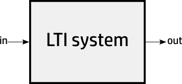
A single-input, single-output LTI system it is fully characterized either by:
its impulse or it step response,
its frequency response.
Measuring LTI systems
When we engineers measure systems, we not use impulses because it is a (very useful) mathematical idealization that do not exist in nature. Instead of this, we like much to use the step response (the response to an stimulus that is zero up to a reference time point and then takes forever a constant amplitude, with a normalized value of one).
We also like much to measure the response to sinusoids of different frequencies. Take into account that the response of a LTI to a sinusoid is always a sinusoid of the same frequency and whichever amplitude and phase shift. What we call the frequency response is just the analysis of the response of the system to input sinusoids of unit amplitude and different frequencies in a certain frequency range.
Remember that we are not forced to measure with an amplitude of one (whatever the unit may be): precisely because the system is linear, if you scale the input, the output will be equally scaled. In practice we measure with signals that have amplitude enough to be large when compared with the noise but not so large that the system shows unlinearities.
The time response and the frequency response are two inseparable sides of the same coin: if you know one, you can calculate of the other.
What happens if the system is not linear? Then the system is no more characterized by the impulse or step response and there is no such a thing as frequency response. The complexity of the problem grows much and typically does not admit an analytical solution.
In this point is good to remember that for semiconductors working in the linear region we use the so called small signal model.
First order systems
From all the LTI systems, the first order ones are my favorite. They are simple and pervasive. Nature is full of first order systems. We saw one in another article in this link.
A first order system is characterized by only two parameters. One is the gain at zero frequency (we use to say Direct Current, DC). The other parameter is one of the following:
time constant (τ, measured in seconds) if we consider the system from the time response perspective.
corner (or cutoff) frequency (Fc, measured in Hz) if we consider the system from the perspective of the frequency response.
Corner frequency and time constant are related between them by a simple formula.
Frequency response
Let us consider a first order low pass system (this one that attenuates the fast variations -high frequency components-). There are also high pass first order systems, but we will concentrate in this.
I am confess I am absolutely ashamed by the beauty and simplicity of the expression of the frequency response when expressed with complex algebra. Before the introduction of this kind of arithmetic, the complexity of the equations make them very awkward to use.
As you have deduced, Go is the frequency response when frequency (F) is zero. If we plot the modulus of frequency response with a logarithmic scale both in frequency and in amplitude, we obtain an extremely elegant figure as shown in next figure. Observe the plot is normalized to a 1 Hz cutoff frequency: you may scale to whichever value you want. The transfer function at corner frequency has -3 dB respect response at DC and this is why the cutoff has another one name: the minus 3 dB frequency.

If this were not enough simplicity, we use the very successful and even simpler Bode approximation. We can model a simplified frequency response by two straight lines that intersect at the corner frequency. In Bode approximation, the modulus is constant up to corner frequency. From this point the response decreases at a rate of 20 dB per decade, or 6 dB per octave, which is the same. Or in other words, ten times less for ten times frequency increase (when counting from corner frequency). See green lines in next figure.

Bode approximation is extremely powerful, but has two dangers you should be aware of:
The approximation is very good just one decade over and below the corner frequency but not in the mid region.
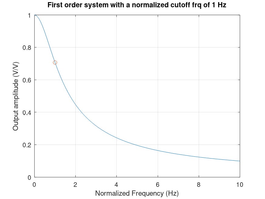
The log-log visualization may suggest that the transfer function decreases fast as you move out of the corner frequency. Nothing further from the truth. The figure that follows is exactly the same drawn before but with linear scale both in amplitude and frequency (X and Y axis). We see that the output amplitude decrease with frequency is exasperatedly slow. Please, never think a filter (of any order) as a system that removes a frequency band, but a one that attenuates a frequency band.
The phase response is the great ignored. If we plot the phase relationship of the output according to the output, we obtain the elegant shown in the next figure. If you ever have to measure the response of a first order system and you can measure phase, use if to precisely characterize the corner frequency. At this point is has a 45 degrees delay and varies fast around this point.

Time response
The time response of an first order system to an step is a decreasing exponential as we saw in mentioned previous article in this link.
Have you noticed that to this point we have used π , j (the complex variable), and e (the Euler number)? They are among of the most relevant numbers in the mathematics.