


Discrete-time first order system implementation
Tricks for implementation in digital circuitry


Imagine that we need to implement a low pass filter of first order in an FPGA or in a CPU. It may surprise you the beauty of its simplicity.
The structure
The following expression defines a discrete time first order system of unity gain. Unity gain means that the steady state response to a step will have the amplitude of the step.
For low pass systems, K will have a positive value which is less than unity.

The rationale of the structure
The output of the filter will be the combination of:
a fraction of the input signal
another fraction of the previous output signal.
These multiplying factors added, are equal to one to keep unity gain.
The value of the multiplying factor K plays an essential role in the speed of the response to the output to input changes,
If we want a filter that responses very fast to input changes, the K term will be close to unity. The weight if the input signal is much higher that the output of the output of the filter, that has low weight.
If we want a very slow filter, the K term will be close to zero which makes the influence of the memory of the filter large and the output of the filter will require long time until the output reaches steady state.
How the structure resemblance with continuous time one
Continuous time low pass filter
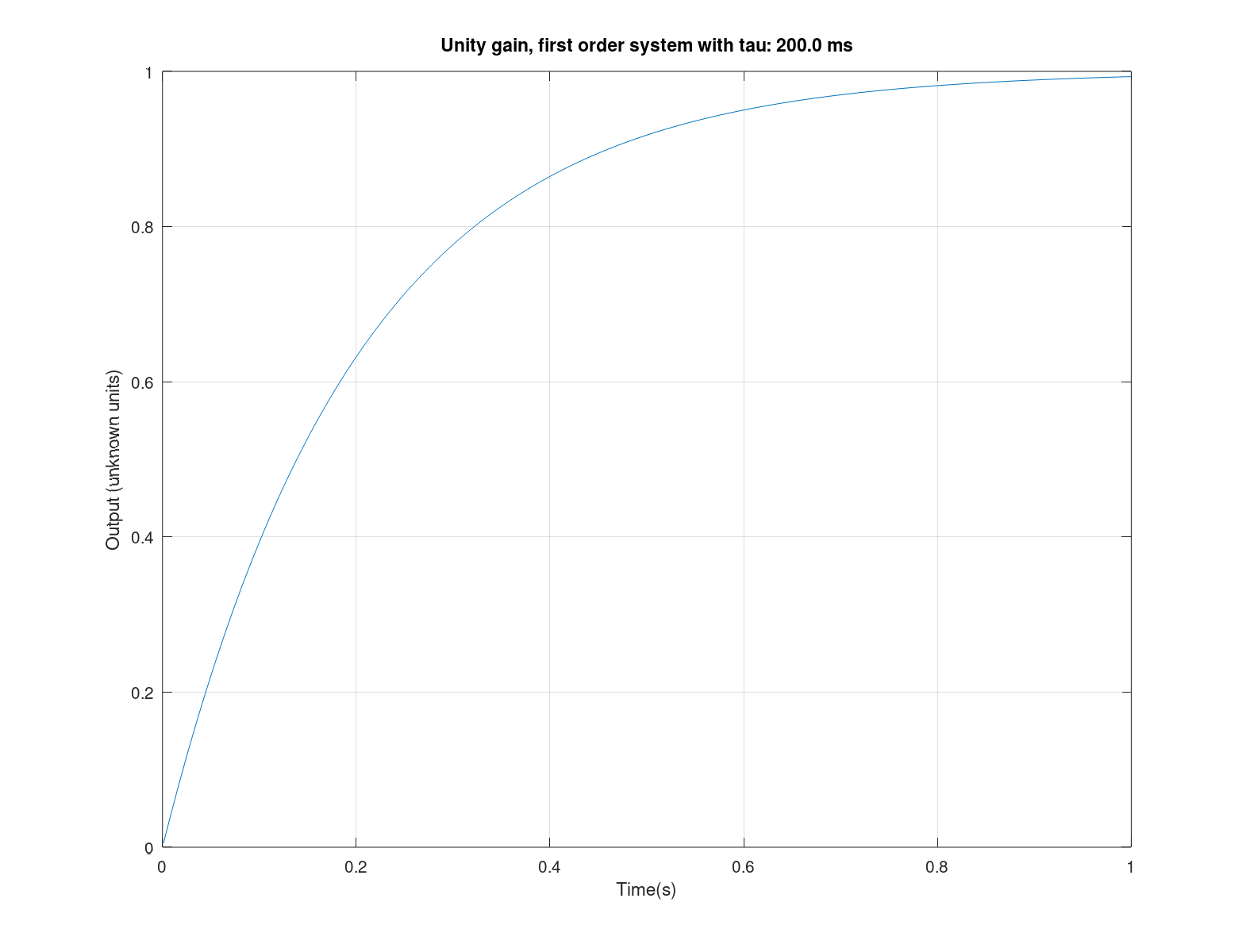
A unity gain first order system is defined by a single parameter: its time constant. The next equation shows the response to a unity amplitude step.
The slope of the response to an step was explained in a previous post (link). Can also be obtained calculating the function derivative and it is:
Discrete time low pass filter
The slope of the response of the discrete time filter to an input step ( x[n] =1 for n>=0) is:
The equivalence between them for a sampled system with sampling period of Ts seconds is:
Next figure shows the equivalence of an step response between continuous and discrete time first order system with unity gain

Implementation of the filter using integer arithmetic
In a discrete time digital system, adding numbers in integer arithmetic is easy to implement. You just have to avoid overloads. The complication comes from multiplication. In order to reduce its number, we can rearrange the expression:
Shown in graphical format results

But there is also another magical trick: dividing by powers of two can be implemented by shifting, an arrangement that is very suitable for HW or SW implementation.
When you do the implementation in logical circuitry (FPGA, for example) it is very common that the shifting becomes configurable and the structure receives the name of barrel shifter. It is very easy to implement a barrel shifter: all the care you need to have when using signed signed arithmetic is to keep sign extension.
For example, the filter element of a closed loop system can use such a configurable structure that allow the whole system to be tuned for optimum performance. In all the systems I have used them the granularity of factor of two has proven to be more than enough.
"La claridad es la cortesía del filósofo"
-José Ortega y Gasset-
No se puede explicar mejor, chaval!!!