

Validating PCAs (1)
Validating PCAs (1)
R&D electronic engineering is about design but also about validating the designed


Historical background
Being teenager, my first fundamental approach to electronics was by reading magazines in the golden age of electronics, with tittles as Elekror, Electronics Today International and few others. Later, in the University I had the opportunity to study the discipline in a much more systematic way. Seen retrospectively, I learned how to design electronics but I did not learned how to validate the electronics that I (or others) have designed. I have been able to check that I am not the only one.
My first test baptism was while working in an University investigation group, a very nice experience parallel to classroom activity. I have had designed for them a quite complex PCB with a large number of TTL MSI chips and the engineering teacher responsible to the project asked me: «How are you going to validate it?».
This is the type of questions that in a fraction of a second triggers an storm in your mind: «of course the design works properly: its mine!», «I have not yet powered the board», «hmm, it is a good question, something could have failed in the design», «or in the manufacturing», «or it has low margin», «but I don't have the slightest idea of how to test this board».
Humbleness was clearly the best option (always is) and in response to it I had the opportunity to receive a real and improvised master class about PCA test. When I arrived late at home, my father asked me for the reason of being so late. I answered: «Dad, today I have learned much more that any other single day at the University».
U model testing
In a very simplified way, what I learned this day is the U-test model.
You have a system you want to test, the so called Unit Under Test (UUT). Then, you have to generate controlled stimulus while you check the response to it. The best scenario is when you have full control of the stimulus and you have the capability to fully check the response to them. By knowing the things that may influence the design, you may be capable to be very sure that the circuit works properly (as expected).
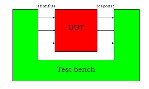
This model will allow you to expose the system to conditions that are very difficult to replicate in real life. This may be in the form of temperatures, waveforms, voltages, currents, test patterns…
Some definitions
This post tittle is (on purpose) about validation. Validation is much more than testing. Testing is just one of the possible forms of the validation. Analytical approach is complimentary. This is so because human nature (and engineering, as a part of it) is so: the ways to reach certainty about something (anything) follows many different and complimentary ways.
It is nice to distinguish different kind of test, and I do not for shake of academical discussion, but because I have the experience that when clarifying the scope some confusion disappears.
Design validation: my Design Under Test is a new board or subsystem. The focus of this test is in being sure that the design is correct and has margin enough.
I should never forget that I am doing an abstraction step: validating a concept by validating one of few units of an implementation.
When I validate a design, it is reasonable to assume that all the components are working properly as specified (although every rule has his exceptions). Let me give an example: it is reasonable not to test the load regulation of a well specified linear voltage regulator, but it reasonable to test the load regulation of the whole system if it includes the PCB traces, which is something that many times is (wrongly) considered ideal. In this example, the manufacturer has done much more characterization than the one you could dream to do.Manufacturing test: When doing it, I will assume that the design is correct, and I need to check that a certain implementation (the UUT) is correct: has been assembled in the right way and with the right components.
Not just the electrical performance needs to be checked, maybe you need to validate thermal one.
Manufacturing test can be done by (optical) inspection, can be in-circuit test (measuring the impedance between different points) or can be functional.
When a board has large sections of digital circuitry, Boundary Scan offers a very convenient way of doing functional test.Integration: many times the boards are a part of a bigger system. You could have a perfect board but it does not integrates properly in its environment, there is no fun: we do not design boards to comply to specifications but to work in actual systems.
Once again, the best scenario is to have the capability to test integration at low level, best if at open loop, when you have more control of the environment.Regression test: it a type of test that is more applicable when there are code changes (either FW of FPGA). Typically not the full design validation is executed but an small fraction of it, those related to the changes in the design or those parts that could be affected.
In the next newsletter post, we will review some real life examples of boards or subsystem validation. Stay tuned!