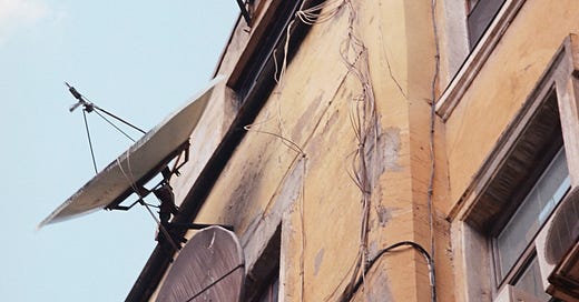
I am sure you have seen many satellite receiver dishes pointing to the sky. Most of you know that the dish acts as big mirror that concentrates all the radio signal received over its surface in a single point in which a device is placed. This device is called Low Noise Block (LNB) or Low Noise Converter (LNC).
(Satellite dishes with LNC in the center - Photo by Ivan Zhuldybin on Unsplash)
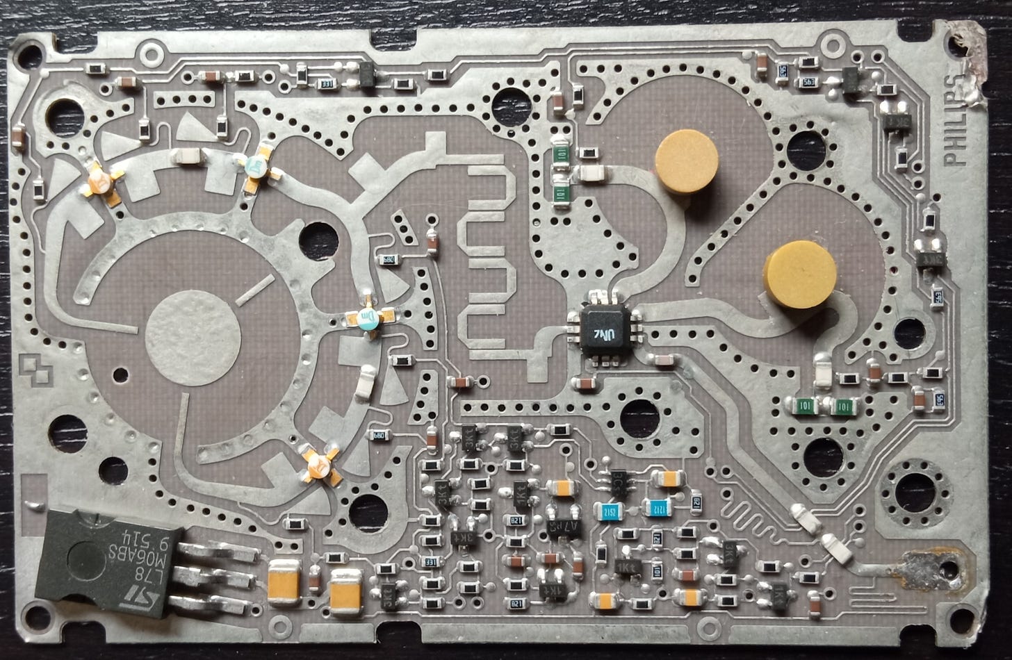
Once I worked in a satellite reception project and I could not resist the opportunity to open a LNC. It was the SC819TB from Philips. I was amazed of its beauty, but delight reaches its maximum level when you understand its operation and this is something I would like to share with you today.
Next figure shows the block diagram of the LNC.
The first surprise is that the receiver has not one antenna but two. The reason for that is that at that microwave frequencies is possible to transmit two different signals with perpendicular polarization with relatively low interference between them. Doing this nearly increases the satellite capacity by two. Take into account that these digital links can operate at signal to noise ratio of 5 dB and less with negligible user error rate thanks to very powerful error coding and error correction techniques. If the orthogonal interference is significantly lower than the high noise level, its effect can be neglected.
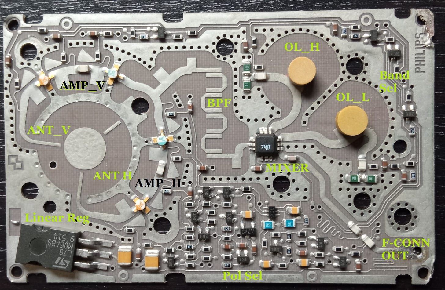
The signal received by each antenna is amplified by two small circular amplifiers (gold and blue colored). Only one branch is supplied at a time. They strengthen the extremely weak signal that was transmitter by a satellite placed in geostationary orbit 37,000 km above the earth's equator.
Every electronic amplifier adds noise to the signal that amplifies. The key point is in the amount of noise it adds. If the device is a low noise one and the amplification is large, the receiver works well with a low size dish, which is cheaper, less invasive and less prone to problems with the wind.
After amplification, the signal enters a mixer, a black square device with three pins in each side. This device supports also two Local Oscillators based on ceramic resonators (circular beige colored). Local oscillator frequencies are 9.75 and 10.6 GHz, and only one of them works at a time.
A mixer, when analyzed in time domain, performs the multiplication of two signals. If you mix two tones, at the output you get also two tones: one with a frequency which is the sum of the input frequencies and other whose frequency is the difference of frequencies.
In algebraic format is:
If you mix a wideband signal with a tone (the so called local oscillator) you get a frequency shift of the wideband signal (also called conversion, and because of that, the name of the device we are studying). You get two wideband signals: a shift of the input signal to an upper frequency (up conversion) and the shift of the input to a lower frequency (down conversion). This later is the one that the LNC uses. The up converted signal has so high frequency that it is very easy to remove by filtering.
Let us have a look to next figure. When you use the Low Local Oscillator at 9.95 GHz, the frequency band from 10.7 to 11.9 GHz shifts to the band from 0.95 to 2.15 GHz. This band is called intermediate frequency band (IF). Our block amplifies it and sends to the indoor Set Top Box (STB) over a coaxial cable.
The reason why the LNC has two oscillators is for the converter to be able to cover a very large bandwidth from 10.7 to 12.75 GHz (2.05 GHz) over a single intermediate frequency band which is 1.2 GHz wide.
I was surprised to know that the total gain is just 54 dB (voltage gain of 500). This is because even an small dish is able to collect a significant amount of energy thanks to its large gain.
How does the LNC knows which polarization or band the user wants to use? The same signal used to supply the bock is used for this purpose. The band is selected by the insertion or not a low amplitude 22 kHz tone over supply voltage, while the mean DC level selects the polarization: 9 to 14 V for H and 16-20 for V.
Next figure shows how the functionality correlates with the actual devices.
Amazing, isn't it?


Hi luis,
very nice analysis of the triple band LNB. I stumbled on your site looking for good pictures for my site and book. I will use the PCB picture in my book with reference to you!
You will find more beautiful LNB pictures on my site https://www.maximus-randd.com/tv-tuner-history-pt5.html#lnb and the books.
Cheers, Pieter