
Multilayer Ceramic Capacitors (MLCC)
How many dielectrics! Are they all the same?

The next figure shows how an MLCC is internally build. It is amazing how such miniature devices can be manufactured in large quantities with so high reliability and at such low cost.
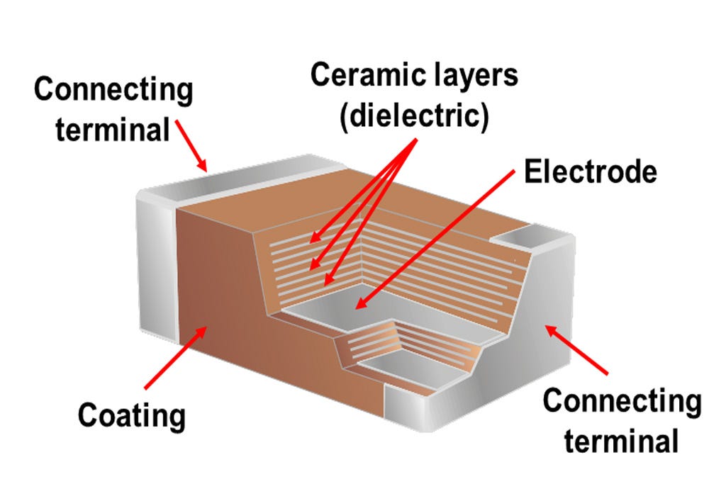
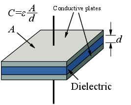
Remember the essence of a capacitor: two plates and a dielectric. It allows to store energy in the form of electrical field.
The most significant parameter that defines the dielectric is its dielectric constant (ε). For simplicity we typically use the relative dielectric constant (εr): how many times is greater than the vacuum one (ε0 , ε = εr ⋅ ε0). The higher the dielectric constant, the higher the capacity. Sometimes we call the dielectric constant DK. Definitely, easier to type.
Once more, when we move from the ideal world of textbooks to real life we find that despite all the effort done by chemists during almost a century, the ceramics we use are not perfect. Many materials have been investigated to get a high dielectric constant (to get large capacity in an small package), dielectric rigidity (related to voltage operating range), robustness to high soldering and rework temperature, high reliability and low cost.
We classify ceramics using an EIA reference. They have established two Types (1 and 2).
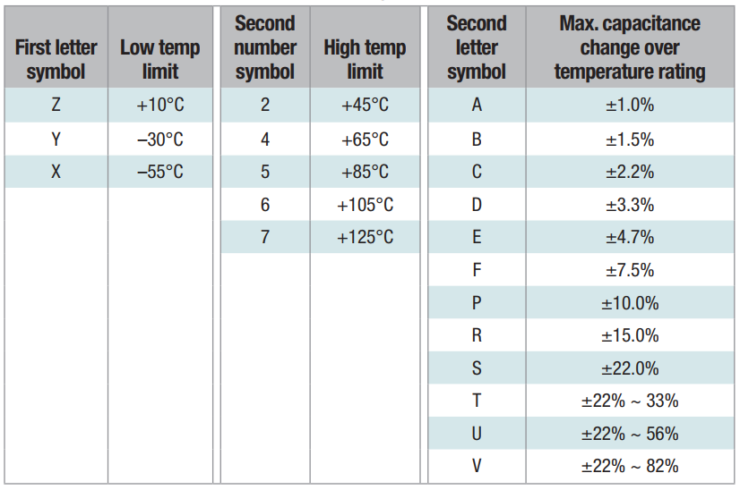
The Type 2 is shown in the following one. I gave taken it from TI's Analog Engineer's Pocket Reference, a EE must have. This table establish the name of a ceramic according to upper and lower working temperature and capacitance variation in the previous temperature range.
The most used dielectrics are:
C0G: It belongs to Type 1 (do not find equivalence in the previous table). It is the best dielectric. Mainly, just the capacitor manufacturing tolerance needs to be taken into account. It offers low capacity variation on voltage and temperature, but as it is a low ε r material, it is available just for (relatively) low capacity/voltage.
X7R: offers a maximum ±15% variation in a temperature range of -55 to 125 ºC. The most used for digital electronics applications.
X5R: offers a maximum ±15% variation in a temperature range of -55 to 85 ºC.
Using other MLCC dielectric (with the only possible exception of Y5V if you insist much) is absolutely discouraged for common applications.
It is needless to say that the higher the dielectric constant of a capacitor, the worst its performance is.
Please note that the EIA nomenclature only describes the temperature change of the ceramic, not the law of change or the ceramic itself.
MOREOVER: This nomenclature may create confusion because there are other hidden aspect in high dielectric constant ceramics (Type 2) that the engineer must be aware of, not just the temperature.
Not just a temperature variation issue
The capacity of a particular capacitor device depends on:
Manufacturing tolerance, which is due to process variation, essentially random.
Temperature (seen before). Deterministic but not linear and unknown, unless reported by manufacturer. Manufacturer/ceramic specific.
DC bias voltage, deterministic and reported by good manufacturers. Manufacturer/ceramic specific.
Ageing, which is difficult to predict. Expected ageing limits reported by good manufacturers
Effect of DC bias
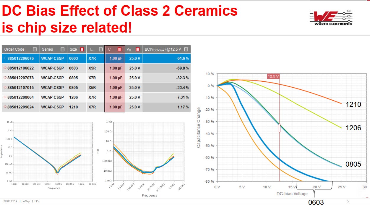
Capacity variation with DC bias voltage can be dramatic for high dielectric constant ceramics (Y5V, X5R and in less extend in X7R) as seen in the following figure provided by Würth. It is not negligible for X7R but definitively is something you need to care of for other dielectrics.
Please, observe they all are capacitors rated for operating at 25 V, but even at half this value, the capacity may be as low as a -70% (one third!) the nominal capacity. Observe the degradation depends not only on dielectric, but also lower size capacitors of the same dielectric degrade more because although they use X7R ceramics, they do not use exactly the same type. Notice the solid blue line is for a X7R capacitor in 0603 package: -62% capacity reduction due to DC bias at half the maximum rated voltage.
Small size capacitors
When you use X7R dielectric and large size capacitors, you may expect small capacity degradation. Typically, we don't apply any derating, although we should in some applications.
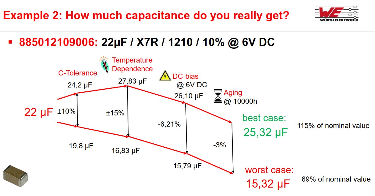
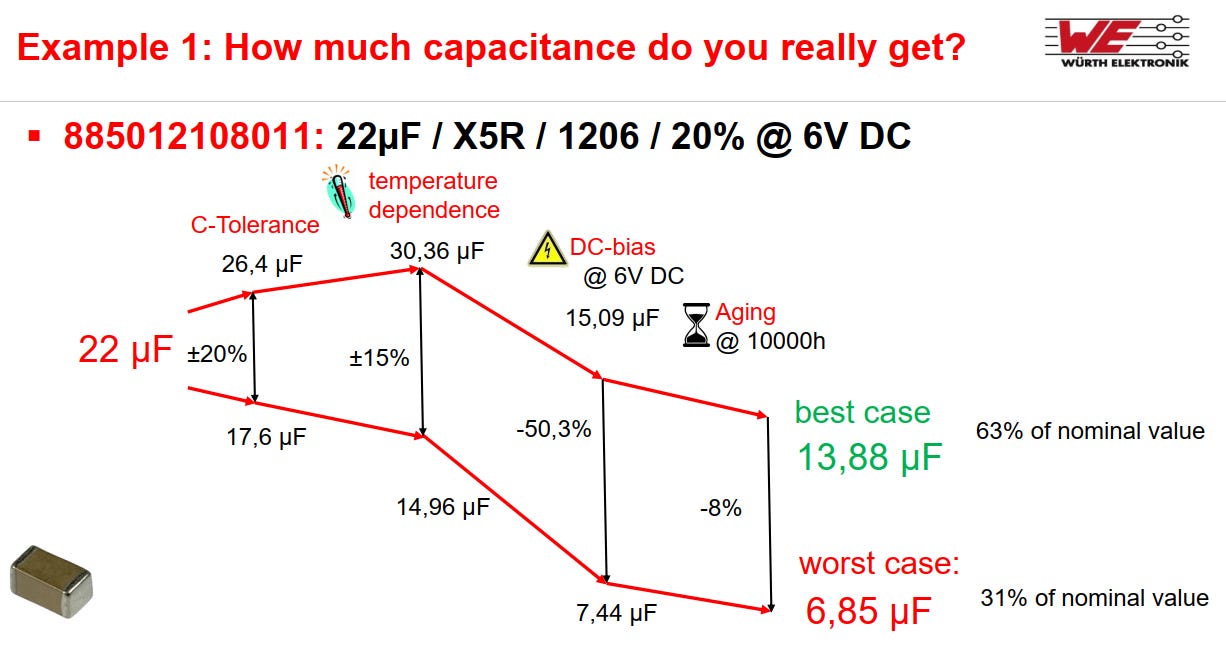
However, for small size or X5R dielectrics, the effect is huge. In the capacitor of the example that follows, the capacity you finally get varies between 1/2 and 1/3 of the nominal capacity. And this is not a worst case because it is a 1206 case. It can be much worse.
Is this really so? An example
There are applications that are more sensible than others.
Decoupling application: As a general rule, neglect capacity variation if you use X7R dielectric but not with others.
Power supply filtering in switched mode (and maybe linear) needs to be carefully studied. One may ask what happens if the final capacity is less that the specified one. The ripple will grow, and this will be irrelevant or absolutely critical, depending on the application.
Let us show a real example: I designed a switched mode PSU to convert 12 V to 6.5 V, having 1.0 A max load. I selected the TI's TPS563200. I used TI's Webench as a help to design the converter. I will concentrate in the selection of devices for the output capacity.
The tool recommends using a 47 μF X5R, 25 V capacitor while reports a derated value of 12 μF. This is the target capacity I should have. Observe it suggest a capacitor with four times nominal value even working at one fourth the rated maximum voltage.
In my design, I could afford a physically large device. I started an iterative process and I ended selecting a 22 μF, X5R, 25 V, 1210 package that there was in the company database. I used muRata SimSurfing. Because there are part from them in the Approved Vendor List of this device.
We can see that the DC bias voltage has great impact in actual device capacity and the nominal 22 μF device has 17.5 μF at 6.5 V (an 80% of nominal value). In my application, by using a device with a rated voltage of 25 V, the capacity reduction due to voltage is not very large. The previous graph is self explanatory: we once again see that the capacity reduction with bias voltage is huge.
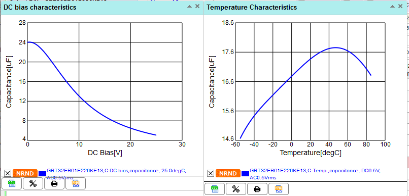
If we consider the temperature, the effect will is small in comparison: for a 6.5 V bias and temperature operating range between 0 and 80 ºC, the capacity will always be over 16.5 μF.
The device has a tolerance of ±10%, which means that we may end having 14.9 μF, a 68 % of nominal value. The large case and high nominal voltage saved the day.
Summary: Guidelines for selecting MLCC capacitor dielectric
For low value capacitors (filters, crystal oscillators) use C0G capacitors (Type 1). Depending on size, you will find them available with capacity of up to 10 nF.
For higher capacity values, try to use only X7R dielectric capacitors.
When you cannot use X7R, do all the math and make a favor to yourself and your colleagues: show it in the electrical diagram.
To learn more
Visit Wurth RedExpert or muRata SimSurfing. It really worth the time. Includes models for EMC components, power, capacitors, ferrites, LED diodes and others (depending on manufacturer). Specifically for capacitors, show capacity variation with temperature and DC voltage and full impedance model.