
Fuses
Know the details to provide long life protection


When you have a board that requires supply protection (and very specially if you need compliance certain regulation standards), one of the most classical solutions is to include a (certified) fuse in the supply line. This tiny device, so simple in its functionality, is a marvel of technology.
The ideal behavior of a fuse is to blow-up when the current that goes across it exceeds its nominal current.
To understand the details, we are going to consider an imaginary board with a real fuse.
Example
Imagine we have a board with a 24 V power supply. Let us consider that due to safety considerations we want to limit its power consumption to less than 100 W. During normal operation the device consumption is much less than this power. If we calculate 100/24, we conclude that we have to use a device that limits current its less that 4.17 A. In practice, we will have to use a 4.0 A certified device.
Imagine that, after an extensive search, we select a protection device from Littel Fuse from the 443 series Slo-Blo(r), manufacturer part number 0443 004. DR. Link to fuse family.
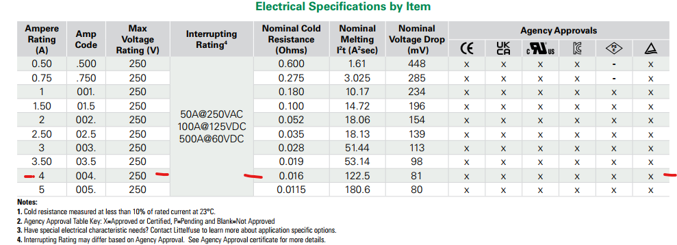
The most basic and easy to understand characteristics of the fuse are included in the first columns:
Fuse rating: 4 A
Voltage rating: 250 V
Cold resistance: 16 mΩ typ
The term cold is significant because the fuse must have a resistance. As current increase, the power dissipation in the fuse increases, it increases its temperature, this produce resistance increase and chain reaction blows the fuse. The only fixed resistance value is the one that it has when it is cold, far from trip point.
The manufacturer also provides in the datasheet two interesting graphs. The first one introduce a current derating due to ambient temperature.
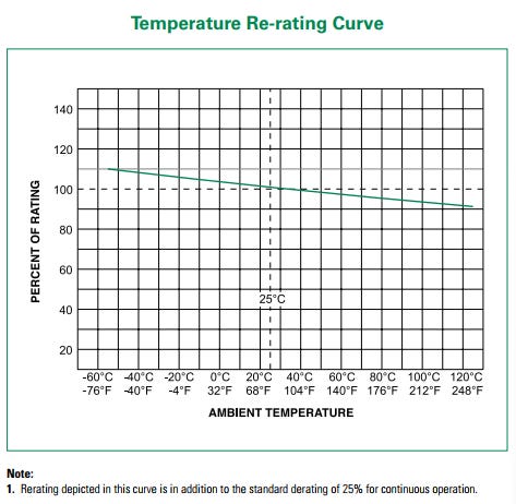
As ambient temperature grows, the current at which the fuse will blow will slightly reduce. For example at ambient temperature of 80 ºC, the current will not be 4 A but 3.8 A (a factor of 0.95).
The second one shows the time the fuse will take to blow depending on the continuous current across it. This fuse will blow up in 3 seconds at 10 A, but at 30 A will blow up in 100 ms. Remember: these data are for constant current.

What does it happen when we have discontinuous current? It appears another term, the so called melting I2t one. This parameters has (implicit) dimensions of energy: it lacks an R term that belongs to the device. The fuse will blow if the current energy pulse is over the reported melting.
Our selected device has a value of 122.5 A^2·s. This is an extremely high value, expect much lower values for typical small size devices.
Let us make an example: imagine that or board has an input capacitor C5, say 220 uF.

When you connect the circuit to a power supply unit (PSU) that has a so called soft startup, the inrush current will be negligible. But it you connect (for example by hand) to an already powered PSU, there will be a very large inrush current.
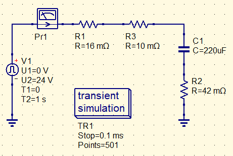
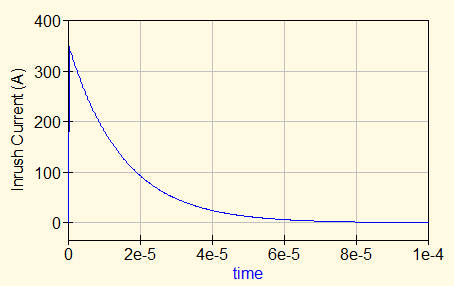
Will it blow the fuse? For a total series resistance of 58 mΩ, peak current will have an impressive figure of 353 A.
In order to simplify calculations and make the explanation more didactic, let us assume that the current consumption of the circuit is very low. The inrush current will have the form of a large pulse with an exponential decay.
The amplitude of the current pulse will be:
where Vpsu is the voltage of the power supply unit and RS the series resistance of the circuit formed by the PSU, the fuse cold resistance, the traces and the ESR (Effective Series Resistance) of the capacitor, a parameter well specified by the manufacturer that is very dependent of component size.
The time constant of the current decay will be
The pulse energy (I2·t) will be
In our example, this results in 0.93 A^2·s.
Every pulse degrades the fuse
But is it enough that the pulse energy is under the fuse reported value? Not at all, it needs to be much lower. Moreover: in every pulse, the device degrades. The manufacturer reports (not in the datasheet but under demand) another graph that says in how many pulses the fuse will open. An this depends on the pulse energy, as expected.
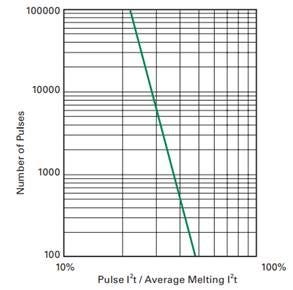
In our example, if the pulse energy is under 22% (26.8 A^2·s) the fuse will not blow, but if is about 50 % (61 A^2·s) will open in 100 pulses.
Exercise for the reader
The previously see electrical diagram include two capacitors, the second one a ceramic one that has much lower ESR that electrolytic ones: the inrush current will be higher. Which would be the inrush current pulse energy due to it?
Curiosity
Long time ago, it was a common practice to include a fuse in series to the loudspeaker in power audio amplifiers to protect the cone of the speaker from overloads (o presence of excessive DC bias). Once I read that this introduced distortion and commenting with Raul, an old and wise engineer, he explained to me that it was likely to be so. Your are placing in the way of signal a resistive device that is build to have a nonlinear behavior. This leads to distortion, does not?. How much distortion is quite difficult to estimate, but it is not negligible considering most speakers offer a load of few ohms.
Worth knowing the hidden details of fuses in order to design very reliable boards.