
A high speed enigma
Sometimes, transmission lines generate surprising effects that challenge our understanding of phenomena. Follows an example of that.


The system
Some time ago, I was working in a large industrial machine. In it, we had to transmit optical encoder information from a moving part to the motor controller. For that, we used quite long (~3 m) twisted pair cable and because of the length and the critical importance of the information, we decided to use differential signalling. In particular, we used LVDS (Low Voltage Differential Signalling).
The surprise
This worked well but once, I had to replicate the system in a test environment that used much shorter cable. It didn’t work: the signals did not arrive at their destination.
Things tend to work in ideal conditions and degrade as they worsen (by increasing distance, more attenuation, reduced bandwidth) but in this time, it was the opposite!
The root cause
The explanation is the following one: the board that receives the encoder signal had an an error: it lacked the termination resistors, with a nominal value of 100 Ω.
An LVDS driver is a current source of 3.5 mA that is invited to flow in one direction or the opposite one, depending on the information to transmit. Such current requires a low value (100 Ω) resistor in the loop. For reasons that we will see later, this resistor is placed at receiver terminals. The current flow across this resistor creates a differential low voltage drop with a peak of 350 mV. The receiver senses this voltage and makes decisions based on it.
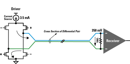
If there are no resistor, the circuit do not work: there is no differential voltage in the receiver. This is what happened with the short cable setup.
But it worked with a long cable!
Why did it work with a long cable? Because in this circumstance, the cable behaves as a transmission line. A LVDS logical state transition may take 1 ns but the cable length was 3 metes long. Being propagation speed of the signal across the cable one half of speed light, it will take 18 ns of the signal to reach it destination.
The driver is no able to ‘see’ the destination to apply Ohm’s Law. Makes a level transition in 1 ns but the load is 18 ns away. Moreover, it will only sense the load when the signals come back to the origin, twice cable delay: after 36 ns, a high speed eternity.
What the driver sees is just a section of the cable that behaves as a pure resistor that has precisely, 100 Ω, the characteristic impedance of the cable for differential mode transmission.
The driver is not able to distinguish if it is driving a discrete (concentrated) load of 100 Ω or a cable with a characteristic impedance of 100 Ω. While signal changes it is the same for it.
The signal will propagate along the cable until it reaches its destination. If it sees a 100 Ω resistance, this would be the end of the tale: no reflections.
However, due to the mistake, this was not the case. When the signal reaches destination sees an open circuit and this creates a reflection. Part of the signal goes back to the source, and then to the destination. It bounces until it reaches the steady state. Every bounce would have a delay: the round trip delay.
Solution of the enigma
The long system cable worked thanks to the distributed nature of the transmission line, because for fast transients, it behaves as a pure resistor. A resistor that has the value of its characteristic impedance (Z0).
With the long cable, the driver sees a 100 Ω load, and this is nice for it.
With the short cable, the driver (which is a current source) sees an open circuit and simply does not work.
Needless to say, we had to modify the board and we had to include the load termination.
I had the satisfaction of having solved a problem (not a very critical one) but over it, I was able to discover the enigma of the long vs the short cable.